


A permeate pump is a non-electric hydraulic device used primarily in a conventional, tank-based reverse osmosis system. It captures pressure from the RO membrane’s brine stream and uses that energy to push purified water—called permeate—into the pressurized storage tank.
The main purpose of a permeate pump is not to increase incoming water pressure. Instead, it reduces the effect of storage-tank backpressure on the RO membrane. Under suitable conditions, this can help the tank fill more effectively, maintain stronger delivery pressure as it fills, and improve the system’s waste-to-product water ratio.
However, an RO permeate pump is not appropriate for every system. Compatibility depends on the RO layout, tank design, tubing and port configuration, automatic shut-off valve, flow restrictor, feed pressure, and pump manufacturer’s requirements. Tankless and integrated-pump systems generally require a different approach.
What Is a Permeate Pump in a Reverse Osmosis System?
A permeate pump is a pressure-exchange device installed in the purified-water and brine pathways of a residential RO system. It normally has separate ports for:
-
Permeate in
-
Permeate out
-
Brine in
-
Brine out
Inside the pump, a piston or diaphragm separates the permeate side from the brine side. Pressurized brine drives the internal mechanism, which moves the purified water toward the storage tank in small cycles.
Because the pump uses hydraulic energy already present in the RO process, a typical residential permeate pump does not need an electrical outlet, motor, or external power supply.
Key Takeaway: A Permeate Pump Uses Brine Pressure to Move Purified Water Into the Storage Tank
The simplest answer to “What does a permeate pump do in a reverse osmosis system?” is this:
A permeate pump uses pressure from the membrane’s brine stream to move purified water into a pressurized storage tank while reducing the backpressure experienced by the RO membrane.
That distinction matters. Without a permeate pump, the membrane must produce water against increasing storage-tank pressure. As the tank fills, its internal air charge is compressed. The resulting water-side pressure pushes back against incoming permeate, gradually reducing the net pressure available across the membrane.
A permeate pump helps separate—or hydraulically isolate—the membrane from much of that tank backpressure. It does not create energy from nothing and cannot push tank pressure beyond the limits imposed by the feed-water pressure and system design.
Permeate, Brine, Storage-Tank Backpressure, and Other Essential RO Terms
Understanding a few terms makes the operation of a permeate pump much easier to follow:
-
Feed water: The incoming tap or well water supplied to the RO system.
-
RO membrane: The semipermeable barrier that separates the feed stream into purified water and a concentrated reject stream.
-
Permeate: Water that passes through the membrane and continues toward the faucet or storage tank.
-
Brine, concentrate, or reject water: The stream carrying a higher concentration of rejected substances toward the drain.
-
Storage tank: A sealed tank that stores RO water against a compressed air charge.
-
Tank backpressure: The resistance created as the storage tank fills and its air charge becomes more compressed.
-
Flow restrictor: A component that maintains the pressure and controlled brine flow required for membrane operation.
-
Automatic shut-off valve, or ASO valve: A hydraulic valve that stops feed-water flow when the tank reaches the system’s shut-off condition.
-
Net driving pressure: In simplified terms, the useful pressure across the membrane after opposing pressure—including permeate-side backpressure—is considered.
The permeate pump operates at the intersection of these flows. Brine provides the driving energy, while permeate is the water being moved into the tank.
What Does a Permeate Pump Do in a Reverse Osmosis System?
A correctly selected and installed permeate pump may:
-
Reduce the influence of tank backpressure on the membrane
-
Help the tank continue filling as its internal pressure rises
-
Increase the amount of usable water stored under pressure
-
Support stronger faucet delivery from a properly functioning tank
-
Improve the relationship between water sent to the tank and water sent to the drain
-
Help a compatible RO system operate more consistently during the later stages of tank filling
The actual improvement varies. Feed pressure, water temperature, membrane condition, filter condition, tank pre-charge, membrane capacity, pump design, plumbing configuration, and water demand can all affect the result.
What a Permeate Pump Does Not Do
A permeate pump does not:
-
Increase the feed pressure entering the RO membrane
-
Replace an electric booster pump where feed pressure is inadequate
-
Repair clogged prefilters or a worn membrane
-
Correct a damaged or waterlogged storage tank
-
Add a new contaminant-removal stage
-
Guarantee a particular tank pressure, fill time, or waste ratio
-
Automatically work with every tank-based or tankless RO system
It also does not directly improve the membrane’s contaminant-reduction capabilities. Its role is hydraulic: it changes how permeate moves into the tank and how much backpressure reaches the membrane.
Permeate Pump vs. Booster Pump: Different Solutions for Different Pressure Problems
A permeate pump and a booster pump address different restrictions.
|
Feature |
Permeate pump |
Booster pump
|
|---|---|---|
|
Primary purpose |
Reduces the effect of storage-tank backpressure |
Raises feed pressure entering the RO system |
|
Energy source |
Pressure in the brine stream |
Electricity |
|
Typical location |
Connected to the membrane’s permeate and brine lines |
Installed on the feed side according to system design |
|
Best suited to |
A compatible tank-based RO system limited by tank backpressure |
An RO system with inadequate incoming pressure |
|
Directly raises feed pressure? |
No |
Yes |
|
Appropriate for all RO systems? |
No |
No; it must match the system design |
If incoming pressure is too low for the RO membrane and controls to operate correctly, recovering brine energy does not solve the underlying feed-pressure problem. A compatible booster pump—or an RO system designed with an integrated electric pump—may be the more appropriate solution.
How Does a Permeate Pump Work?
A permeate pump works as a small hydraulic pressure exchanger. It channels the brine and permeate streams through separate internal chambers so that energy from the brine side can drive permeate toward the tank.
The Two-Chamber Pressure-Exchange Principle

A typical pump contains two hydraulic sections separated by a piston, diaphragm, or similar moving assembly. The fluids do not mix.
On one side, brine from the membrane enters under pressure. On the other side, permeate produced by the membrane enters at a lower flow rate. Brine pressure moves the internal assembly, displacing a small volume of permeate toward the storage tank.
When the pump reaches the end of part of its stroke, internal valves redirect flow and the assembly resets. This repeating action creates the characteristic pulsing or cycling that may be heard under the sink.
How Brine-Side Pressure Drives Permeate Toward the Tank
In a standard RO system, brine retains some of the feed-water pressure after moving across the membrane housing. Without energy recovery, that stream passes through the restrictor arrangement and ultimately goes to the drain.
A permeate pump uses part of that available hydraulic energy before the brine is discharged. The brine side drives the internal mechanism, while the permeate side transfers purified water into the tank.
This does not mean brine becomes product water. The two streams remain separated. Brine supplies the mechanical force; permeate remains the purified stream.
The Permeate Pump Cycle From Membrane to Storage Tank
The cycle can be summarized as follows:
-
Feed water reaches the RO membrane.
-
The membrane separates the flow into permeate and brine.
-
Permeate enters the pump’s permeate-side inlet.
-
Brine enters the separate brine-side inlet.
-
Brine pressure moves the internal piston or diaphragm.
-
The movement pushes a small volume of permeate through the permeate outlet toward the tank.
-
Brine leaves through the brine outlet and continues to the drain.
-
Internal valves reset the mechanism, and the cycle repeats while the membrane is producing water.
Because the movement occurs in small increments, intermittent clicking, pulsing, or vibration can be normal. The exact sound and cycle rate depend on the pump, water pressure, system flow, and stage of tank filling.
Why a Permeate Pump Does Not Require Electricity
The pump is powered by pressure already present in the brine stream. It does not use an electric motor to raise feed pressure.
This makes the device useful in under-sink cabinets where an electrical outlet may not be available. Non-electric operation does not make installation universal, however. Correct hydraulic routing is essential, and the pump still needs sufficient water flow and pressure to cycle.
How Isolating the Membrane From Tank Backpressure Changes RO Performance
As a conventional storage tank fills, pressure on its water side rises. Without a permeate pump, that pressure acts against the membrane’s permeate outlet. The difference between feed-side pressure and permeate-side pressure becomes smaller, so product-water production slows.
The membrane may still send brine to the drain during this slower production period. That is one reason the waste-to-product ratio can become less favorable near the end of a tank-filling cycle.
By moving permeate into the tank and shielding the membrane from much of that resistance, a permeate pump allows the membrane to operate under more favorable hydraulic conditions. The practical value is greatest when storage-tank backpressure—not another defect—is the main constraint.
Reverse Osmosis Permeate Pump Benefits and Limitations
The main reverse osmosis permeate pump benefits involve tank filling, usable storage pressure, and hydraulic efficiency. They are not fixed performance guarantees.
Can a Permeate Pump Improve RO Tank Pressure or Filling Performance?
Yes, a compatible permeate pump can improve tank filling by continuing to move product water into the tank as tank pressure increases. This may allow the tank to store more usable water under pressure and provide stronger flow at the faucet than the same system would provide when tank backpressure substantially limits filling.
Several qualifications apply:
-
The storage tank must be functional and correctly pre-charged.
-
Feed pressure must be sufficient for the RO system and pump.
-
Filters and the membrane must not be clogged or exhausted.
-
The pump must be plumbed and oriented correctly.
-
The ASO valve and flow-restrictor arrangement must be compatible.
-
The pump cannot create pressure beyond the limits of the source pressure and system design.
If a full tank has weak faucet flow, inspect the tank, faucet pathway, post-filter, and tubing before assuming a permeate pump is the solution.
How Reduced Backpressure Can Improve Tank-Filling Efficiency
A standard pressurized tank becomes progressively harder to fill. Early in the cycle, tank backpressure is relatively low. Later, the membrane must work against greater resistance.
A permeate pump changes this relationship by using brine pressure to push water into the tank. The membrane can continue producing permeate without directly experiencing the same degree of increasing tank resistance.
The result may be more effective filling during the later part of the cycle. Whether that produces a noticeable reduction in total fill time depends on the complete system, including membrane output, feed pressure, feed-water temperature, tank size, and household demand.
How a Permeate Pump May Improve the Waste-to-Product Water Ratio
An RO waste ratio compares the volume discharged as brine with the volume collected as permeate. A permeate pump may improve that ratio because the membrane can produce water more effectively while the tank is filling, especially as tank pressure rises.
Some commercial descriptions attach large percentages to this benefit. Those figures should not be treated as universal. Actual savings depend on test conditions and system design, including:
-
Incoming water pressure
-
Feed-water temperature
-
Membrane capacity and condition
-
Flow-restrictor selection
-
Tank pressure and pre-charge
-
Pump model and installation
-
Automatic shut-off behavior
-
Frequency and volume of water use
The reliable conclusion is directional: reducing permeate-side backpressure can improve the relationship between product water and drain water in a compatible tank-based RO system. The exact change must be evaluated at the system level.
Does a Permeate Pump Improve Water Quality or Contaminant Removal?
A permeate pump does not add filtration media and does not introduce another rejection barrier. The RO membrane and other treatment stages remain responsible for contaminant reduction.
Reducing backpressure may help a membrane operate closer to its intended hydraulic conditions, but this should not be presented as a separate or guaranteed water-quality improvement. If taste, odor, TDS, or contaminant reduction is the concern, inspect the membrane, filters, system configuration, maintenance status, and product-specific performance documentation.
Pulsing, Noise, Added Connections, and Other Practical Trade-Offs
A permeate pump adds components and tubing connections to the cabinet. Practical trade-offs can include:
-
Audible clicking or pulsing while the pump cycles
-
Minor vibration if the pump or tubing is not secured
-
More fittings that must be checked for leaks
-
Additional space requirements under the sink
-
More complex troubleshooting
-
Compatibility restrictions involving valves, tubing, and system manifolds
Pulsing by itself does not necessarily indicate a defect. Continuous drain flow after the tank should be full, failure to cycle, leaking fittings, or no improvement in filling performance warrants further inspection.
How Do I Know Whether a Permeate Pump Is Compatible With My RO Setup?
Compatibility is most likely when the system is a conventional under-sink RO unit with a pressurized storage tank and accessible, clearly identified permeate and brine tubing.
It should never be assumed from appearance alone. Check the RO system manual, pump installation diagram, tubing size, port labels, flow-restrictor position, ASO arrangement, and warranty terms before making changes.
Compatibility Is Most Likely With a Conventional Tank-Based Under-Sink RO System

A traditional residential RO setup often includes separate prefilter housings, a membrane housing, an ASO valve, a drain connection, and a pressurized storage tank. This type of accessible layout is the common application for a permeate pump.
Homeowners comparing system designs can review Frizzlife’s selection of under-sink reverse osmosis systems, but compatibility with an add-on pump must still be confirmed for the specific model. Do not infer compatibility simply because a system is installed under a sink.
Where the Permeate Pump Connects to the Permeate and Brine Lines
At a conceptual level:
-
The permeate path runs from the membrane toward the pump’s permeate inlet, then from the permeate outlet toward the tank.
-
The brine path runs from the membrane to the pump’s brine inlet and from the brine outlet toward the drain, with the flow restrictor and valves positioned exactly as specified in the manufacturer’s diagram.
The exact routing is not universal. The placement of check valves, the ASO valve, and the flow restrictor may differ by system and pump design. Follow the diagram supplied for both products rather than relying on port position or tubing color alone.
Automatic Shut-Off Valve and Flow-Restrictor Compatibility
A tank-based RO system normally uses an ASO valve to stop feed flow after the storage tank reaches its shut-off condition. A permeate pump changes the pressure relationships that the valve responds to, so the ASO must be suitable for the intended plumbing configuration.
The flow restrictor is equally important. It creates the controlled brine flow and membrane pressure required for RO operation. Removing it, bypassing it, placing it incorrectly, or pairing incompatible components can prevent proper membrane production or pump cycling.
Because valve configurations vary, generic installation advice should not replace the manufacturer’s plumbing diagram.
Mounting Orientation Is Model-Specific: Follow the Outlet-Port Instructions
For a permeate pump whose instructions specify upward-facing Permeate Out and Brine Out ports, that orientation is essential. It allows trapped air to escape from the chambers and helps the hydraulic mechanism prime and cycle.
If those outlet ports face downward or trap a high pocket of air, the pump may become air-locked. Symptoms can include:
-
No cycling sound
-
Irregular or incomplete strokes
-
Little or no tank filling
-
Brine flow without effective permeate transfer
-
Cycling that starts only after tubing is moved or pressure is released
Mounting requirements are model-specific, so the pump’s installation manual takes priority. Do not rotate or mount a device in an unapproved position merely to fit the cabinet. If the required orientation cannot be maintained, the available space is not suitable for that installation.
Why Port Direction, Tubing Size, and Manufacturer Instructions Matter
Permeate and brine ports are not interchangeable. Reversing an inlet and outlet can prevent cycling, interfere with shut-off behavior, or send water through an unintended path.
Before connecting tubing:
-
Read every port label directly on the pump.
-
Confirm the required direction of flow.
-
Match the tubing and fittings specified by the manufacturers.
-
Make clean, square tubing cuts.
-
Insert tubing fully into approved quick-connect fittings.
-
Keep lines free of kinks and sharp bends.
-
Leave enough access to inspect each connection.
-
Confirm that check valves and restrictors remain in their specified locations.
After pressurizing the system, inspect every new connection for leakage.
Why Tankless, Integrated-Pump, and Proprietary RO Designs Require Separate Verification
A tankless RO system does not experience storage-tank backpressure in the same way as a conventional pressurized-tank system. Many tankless designs also use integrated electric pumps, sensors, control boards, flushing programs, and proprietary waterways.
Adding a generic permeate pump to such a design may be unnecessary or incompatible. It could also interfere with flow sensing, flushing, drain control, or shut-off logic.
If avoiding a storage tank and maintaining direct-flow operation are the priorities, compare purpose-built tankless reverse osmosis systems rather than assuming a tank-based system should be modified. Always verify model-specific installation and warranty requirements.
A permeate pump is mainly intended for compatible tank-based RO systems. If you prefer a purpose-built tankless setup, compare these Frizzlife options instead.
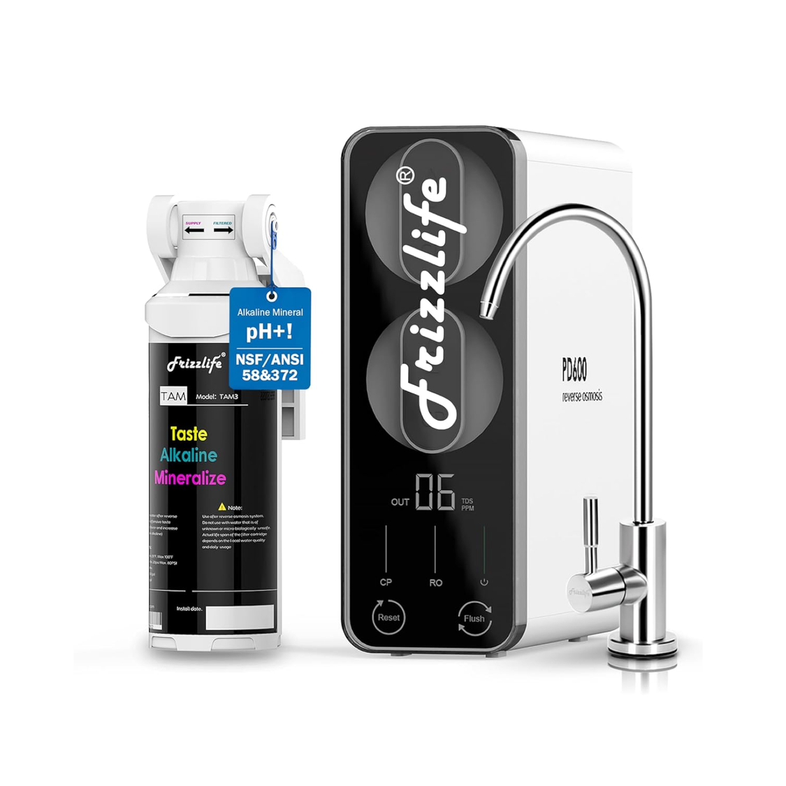
A tankless under-sink reverse osmosis system with alkaline remineralization for users who prefer a compact RO setup without a pressurized storage tank.
View PD600-TAM3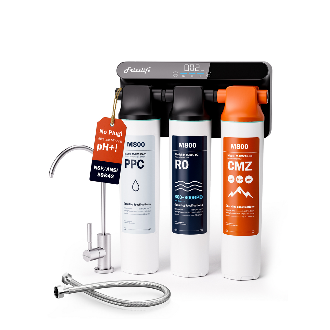
A non-electric tankless reverse osmosis system designed for under-sink filtration without relying on a traditional pressurized storage tank.
View M800
Already own a Frizzlife RO system? Find replacement filter cartridges by system model to keep your filtration setup properly maintained.
Find Replacement FiltersInstalling and Verifying an RO Permeate Pump
Installation should begin with diagnosis, not tubing changes. Confirm that tank backpressure is actually contributing to the performance problem and that the existing RO system is otherwise operating correctly.
Pre-Installation Checklist: System Layout, Feed Pressure, Tank Condition, and Available Space
Before installing a permeate pump for an RO system, verify:
-
The system uses a compatible pressurized storage tank.
-
The membrane’s permeate and brine lines are accessible.
-
All four pump ports can be identified.
-
The pump can be mounted in its required orientation.
-
Feed pressure is within the operating requirements of both products.
-
The prefilters and membrane are in serviceable condition.
-
The tank holds its specified air pre-charge when empty.
-
The ASO valve and check valves operate correctly.
-
The flow restrictor is present and correctly positioned.
-
Tubing and fittings match the specified size.
-
The cabinet provides enough room for secure mounting and leak inspection.
-
The system and pump instructions do not prohibit the proposed modification.
Depressurize the system and shut off the feed supply before disconnecting tubing. If the system layout is unclear, use a qualified installer rather than experimenting with the water pathways.
Common Installation Errors That Prevent a Permeate Pump From Cycling
Common causes of failed operation include:
-
Connecting permeate tubing to brine ports
-
Reversing the inlet and outlet on either side
-
Mounting the pump in a position that traps air
-
Leaving a tubing line kinked or pinched
-
Failing to open the storage-tank valve
-
Installing a check valve backward
-
Misplacing, removing, or bypassing the flow restrictor
-
Using an incompatible ASO arrangement
-
Attempting to run the pump with insufficient feed flow
-
Leaving the membrane or filter housings air-bound after service
-
Connecting the pump to an unsupported integrated manifold
Work from the system diagram rather than assuming that tubing colors are standardized.
How Do I Know the Permeate Pump Works After Installation?
A working permeate pump should cycle while the membrane is producing water and the storage tank is accepting water. Depending on the pump and operating conditions, you may hear periodic clicks or feel small pulses through the pump body or connected tubing.
You can verify operation without relying on sound alone:
-
Start with the storage tank partially or fully emptied.
-
Open the feed-water and tank valves according to the system instructions.
-
Allow the RO system to begin producing water.
-
Confirm that brine is moving toward the drain.
-
Listen or feel for repeated pump cycles.
-
Allow time for the tank to fill progressively.
-
Confirm that the system eventually reaches its normal shut-off condition.
-
Inspect all new tubing connections for leaks during and after the filling cycle.
Do not judge performance from the first few moments after installation. Air introduced during plumbing work may need to purge before the pump settles into a regular cycle.
If the Pump Does Not Cycle: Check Air Lock, Port Direction, Valves, and Water Flow
If the pump remains inactive:
-
Confirm that feed water is reaching the RO system.
-
Verify that the membrane is producing both permeate and brine.
-
Check that the tank valve is open and the tank can accept water.
-
Read the port labels and confirm all four flow directions.
-
Check the required mounting orientation, especially whether the outlet ports must face upward.
-
Look for pinched tubing and closed valves.
-
Verify that the restrictor and check valves are correctly placed.
-
Purge trapped air according to the manufacturer’s instructions.
-
Check whether the ASO valve is stuck or prematurely closed.
If brine is flowing but no permeate reaches the tank, stop the system and recheck the permeate pathway and pump orientation.
If the Tank Still Fills Slowly: Check Feed Pressure, Filters, Membrane, and Tank Pre-Charge
A working pump cannot compensate for every restriction. Slow filling can still result from:
-
Low incoming pressure
-
Cold feed water
-
Clogged sediment or carbon prefilters
-
A worn, fouled, or incorrectly sized membrane
-
A blocked post-filter or tubing line
-
Incorrect tank air pre-charge
-
A damaged tank bladder
-
An undersized or incompatible pump
-
Improper restrictor selection
-
A malfunctioning ASO or check valve
Test the system methodically. Compare production with the tank isolated only if the system or pump manufacturer provides a safe procedure for doing so. Avoid adjusting tank pre-charge while the tank contains water because that produces an inaccurate reading.
When to Stop Troubleshooting and Consult the System or Pump Manufacturer
Stop and seek technical assistance if:
-
The plumbing diagram cannot be matched confidently to the actual system.
-
The pump leaks from its body or ports.
-
The RO system does not shut off after the tank fills.
-
Water routes unexpectedly to the drain or faucet.
-
Feed pressure falls outside the stated operating range.
-
The system uses an integrated or proprietary manifold.
-
The proposed modification could affect warranty coverage.
-
Repeated air locking continues despite correct orientation.
-
A valve or restrictor location is uncertain.
Persistent drain flow can waste water and may indicate an ASO, check-valve, tank, or installation problem rather than normal permeate pump operation.
Should You Add a Permeate Pump to Your RO System?
Choose a permeate pump only after confirming that the system is compatible and storage-tank backpressure is a meaningful part of the problem. Avoid treating it as a universal upgrade for slow flow, high drain volume, or poor water quality.
Only Works if Tank Backpressure Is the Real Bottleneck
The main value of a permeate pump is that it offsets the resistance created by the pressurized tank during filling. If the membrane produces water normally when tank pressure is low but slows substantially as the tank fills, backpressure may be limiting performance.
That does not mean every late-cycle slowdown is abnormal. Some slowing is inherent to a pressurized-tank design. The question is whether the system’s performance, drain use, and usable storage would benefit enough to justify another component.
A permeate pump will have limited value if the real bottleneck is upstream of the tank. For example, a clogged prefilter restricts feed flow before water reaches the membrane. A permeate pump on the product side cannot remove that restriction.
Signs Tank Backpressure May Be Limiting RO Performance
A permeate pump may be worth investigating when:
-
Production is acceptable with an empty tank but drops sharply as it fills.
-
The tank stops accepting water well before expected source-pressure limits.
-
Drain flow continues while product-water production becomes very slow.
-
The tank and filters are functional, but usable stored volume or delivery pressure remains disappointing.
-
The system is a conventional tank-based design with accessible, compatible plumbing.
These signs are diagnostic clues, not proof. Tank pre-charge, membrane condition, feed pressure, and ASO operation should be checked first.
Does Every RO System Need a Permeate Pump?
No. Many RO systems are designed to perform without a separate permeate pump. Others use an integrated electric pump or a tankless direct-flow configuration.
A permeate pump is an optional hydraulic component for certain tank-based systems. It is most relevant when:
-
Tank backpressure materially limits membrane operation.
-
Improved tank filling or hydraulic efficiency is a priority.
-
The system’s valve and tubing layout supports the pump.
-
The owner accepts added connections, possible pulsing, and additional troubleshooting complexity.
If the current system fills the tank adequately, shuts off correctly, and meets household demand, adding a pump may provide little practical value.
Permeate Pump Decision Table
|
Symptom or goal |
Likely issue |
Best next step |
Permeate pump fit
|
|---|---|---|---|
|
Production starts normally but falls as the tank fills |
Tank backpressure may be limiting production |
Check tank pre-charge, ASO function, and compatibility |
Potentially useful |
|
Production is slow even with an empty tank |
Low feed pressure, clogged filters, membrane restriction, or cold water |
Diagnose feed-side conditions first |
Unlikely to solve the cause |
|
Tank fills, but faucet flow is weak |
Tank, post-filter, faucet, or tubing restriction |
Check delivery-side components |
Usually not the first solution |
|
Excessive drain flow continues after the tank is full |
ASO, check valve, tank, or installation fault |
Shut down and troubleshoot the control system |
Do not add a pump until repaired |
|
Incoming pressure is below system requirements |
Inadequate feed pressure |
Evaluate a compatible booster-pump solution |
Not a substitute |
|
Goal is better late-cycle tank filling |
Tank backpressure |
Verify conventional tank-system compatibility |
May be appropriate |
|
System is tankless or uses integrated controls |
Different hydraulic architecture |
Follow model-specific design and support guidance |
Usually incompatible without explicit approval |
|
Water quality or TDS is the concern |
Membrane, filters, maintenance, or source-water conditions |
Evaluate treatment performance and service status |
Does not add contaminant removal |
|
Pump cycles but tank remains slow to fill |
Upstream restriction, tank problem, mis-plumbing, or incompatible pump |
Check filters, membrane, tank, valves, and ports |
Troubleshoot before drawing conclusions |
References
https://patents.google.com/patent/US5460716A
https://info.nsf.org/Certified/DWTU/Listings.asp?ProductType=&Standard=058&hdModlStd=ModlStd